Here is a build-log of how I customized this StarTrix rocket figure to create a pretty glow effect.
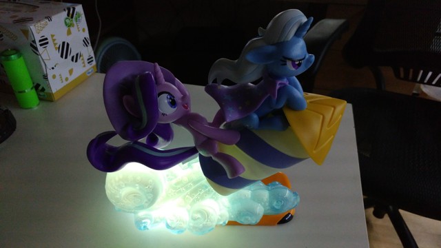
So, a couple of weeks ago, out of curiosity, I put my phone underneath the famous StarTrix rocket figure, and activated the flashlight.
The resulting effect looked pretty damn cool, and I wanted to make something that can recreate this effect without having to have my phone under the figure 24/7.
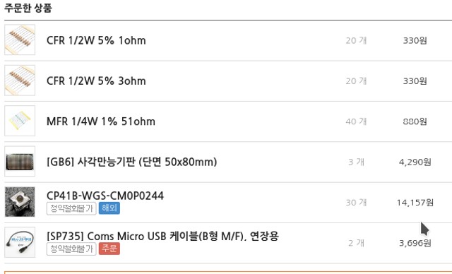
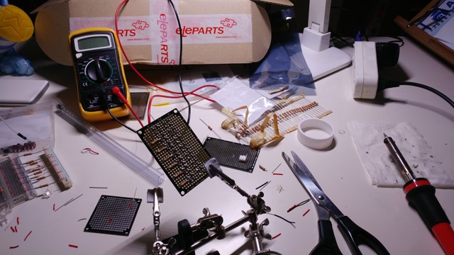
First, buying the necessary supplies. The LEDs were a bit expensive...
Of course, I used many parts/tools I had at home, so this is not a complete parts lists for this project.
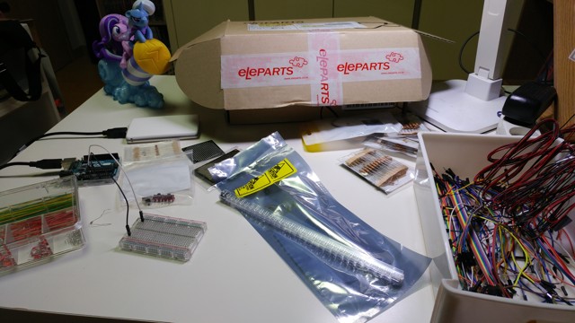
The parts are all here, so let's begin!
Starting off with a bit of soldering...
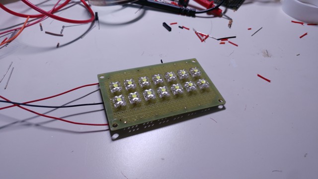
The goal here is to make a 2x7 matrix of LEDs, like so.
The LEDs used are CP41B-WGS from Cree.
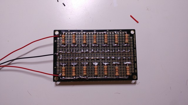
Crappy soldering job.
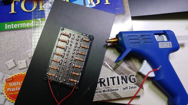
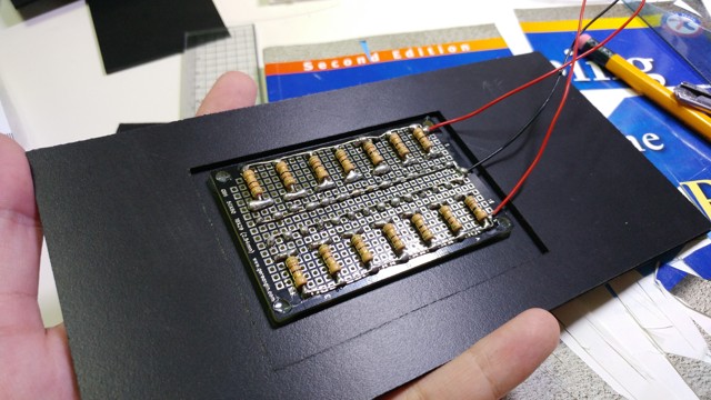
14 LEDs are connected in parallel. 51Ω current-limiting resistors are connected to each LED. Each LED takes 30mA, with a combined total of 420mA @ 5V.
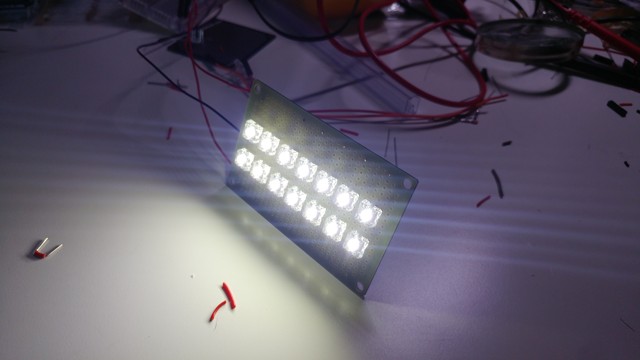
...It works! It's so bright that it hurts to look at.
With the LED circuitry done, we move onto the figure itself.
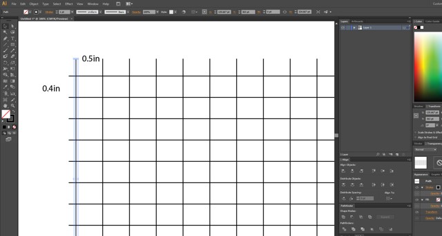
With a bit of help from our trusty friend Illustrator...
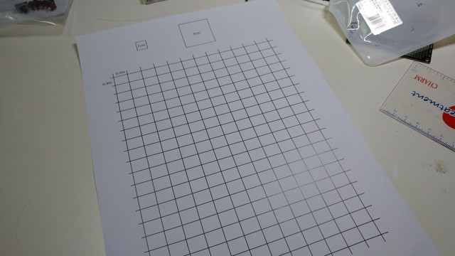
I printed out a "guide" sheet...
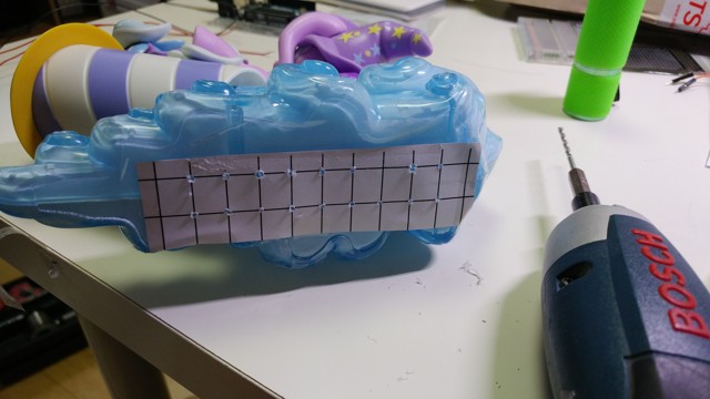
And then taped this sheet to the bottom of the figure, drilling where the grid lines meet.
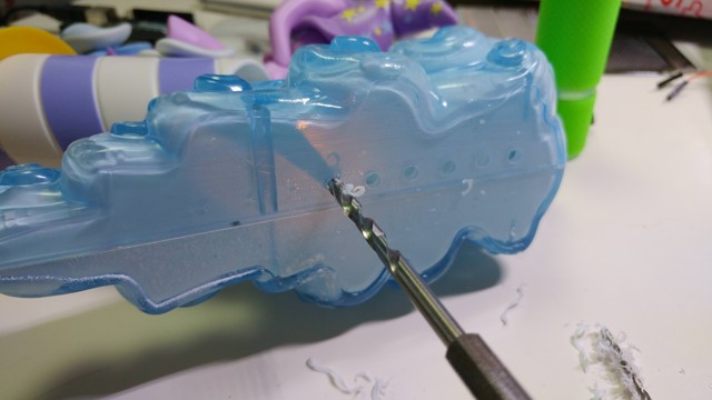
Drill away!
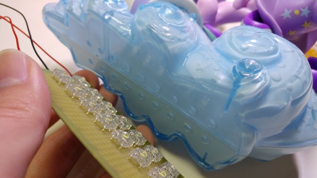
The LEDs' dome will fit exactly into the drilled holes.
While you can just shine the LEDs directly at the figure without any holes, drilling a hole and then fitting the LEDS into the hole creates a much, much brighter result.
Now onto making the "chassis" or "base" of the LED-thingy.
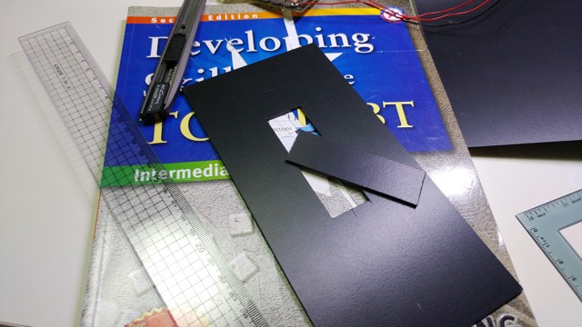
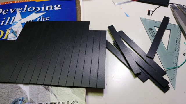
I used a PVC Foamboard, as it looks nice, is strong, and is relatively easy to cut and glue together. I used an ordinary knife and a ruler to cut the board into the dimensions I want.
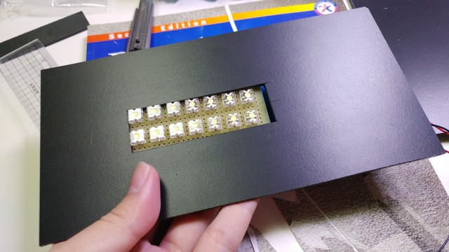
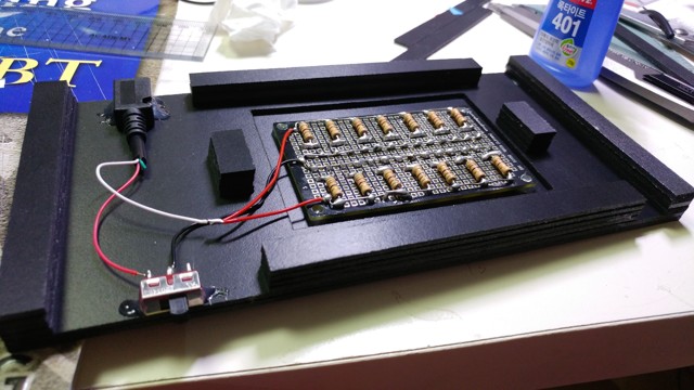
The LED-board will fit inside the base like so.
I used hotglue to glue the base and the LED-board together.
Added another layer of foamboard and superglued it for extra rigidity - don't want the base to bend under the weight of the figure!
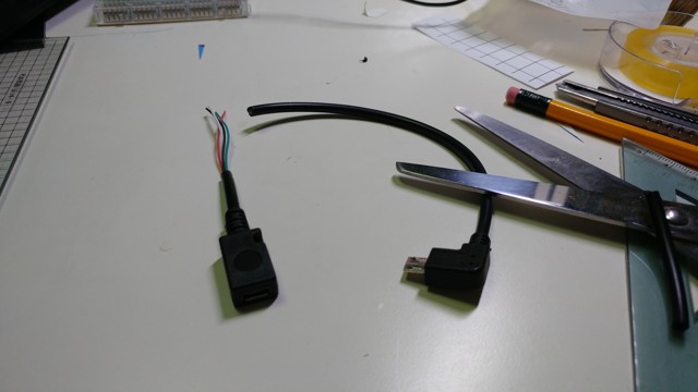
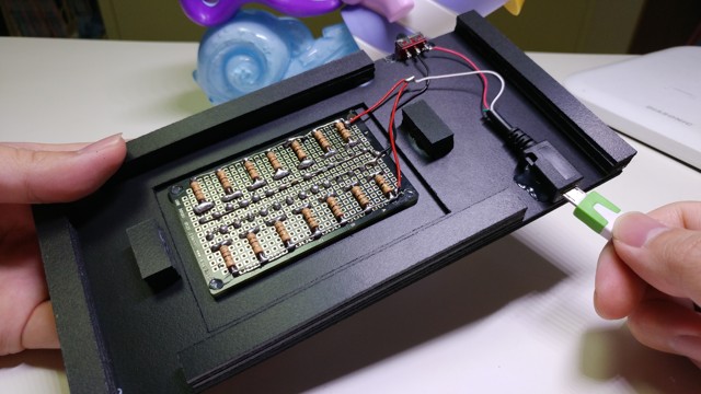
The 5V Power for the LEDs will be provided through a Micro USB port - for this, I had to cut a Micro USB extension cable in half.
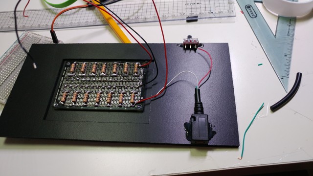
For some reason, the Ground rail was connected to the red wire, and the +5V rail was connected to the white wire... and apparently green and black are data wires. wat.
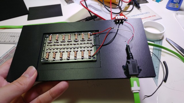
With the Micro USB receptor and a toggle switch hotglued on, it's time for more soldering!
The completed circuit.
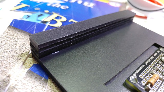
I used the same PVC Foamboard to make the "legs" of the base...
...By simply stacking layers of foamboard and gluing it together with superglue.
"Legs" completed! Finally this thing can stand upright on its own.
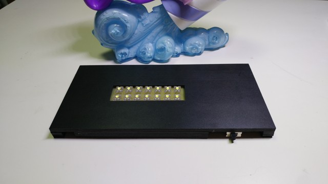
And now, the finished base! Looks very nice and clean.
...as long as you don't flip it over. I've left the bottom open for potential future maintenance.
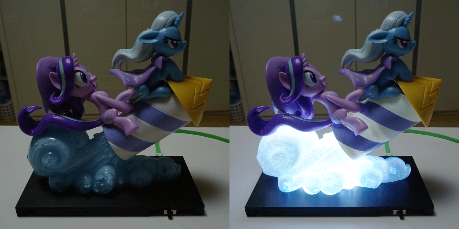
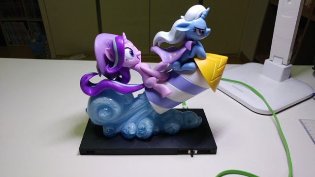
Here it is, lights off, with the figure on top...
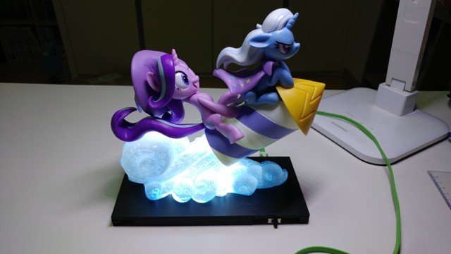
And here it is with the lights on!
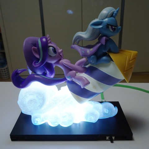
The finished product again.
This was also uploaded to:
Twitter![]()
DeviantArt![]()
Derpibooru![]()
Derpibooru![]()
